System Design
Description
An autonomous, fan propelled robot that will traverse windows, overcome obstacles and effectively clean window surface through an actuated, fluid dispensing cleaning arm. The robot has been designed to operate on two wheels located in the center of the chassis. The 90 mm wheels are large enough to allow for effective window barrier crossing, and silicon wheel treads increase traction against the surface. Micro metal gear motors provide enough torque to overcome robot weight and normal force against the window due to thrust. Two fan motors rotate propellers so that enough thrust force is produced for the robot to overcome gravity. Two cleaning arms project from the top and bottom of the robot. These arms dispense cleaning liquid while pressing against the window and they provide balance for the chassis since the wheel setup requires a third arm to keep the chassis from tipping. Control of all motors is facilitated through an STM microcontroller. Ultrasonic sensors and an IMU also relay information to the microcontroller to allow for robot autonomy during operation.
Our original design had issues and therefore we went back to the drawing board. In order to keep our weight down and the power generated by fans to a minimum we decided to use a hover board like design.
Brainstorming
Part 1

In our original design we wanted to create a robot with three omnidirectional wheels. It would be similar to a tri-copter design.

Part 2


Locomotion
For locomotion we are using micro metal gear motors with a 298:1 gear ratio that allows enough torque to be expelled to overcome both the entire robot’s weight and the forces against the wheels due to fan thrust.
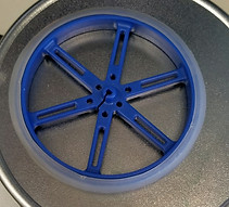
The chosen wheels are 70 mm in diameter to allow for effective window barrier crossing, and a sticky silicon tread has been added overtop the wheels’ circumferences to aid in traction.
During testing, the wheels generally could provide enough torque to traverse the window. Issues did arise with wheel slippage however. The cleaning solution had to be altered to remedy this issue. Another major weakness point of this locomotion system was the delicate motors. While lightweight, the micrometal gears would wear easily. This created a large amount of backlash and reduced the amount of torque the motors could provide.
The controller subsystem utilized the STM32L152RC microcontroller featuring a 32-bit ARM® Cortex® -M3 CPU. The application development was done using the Discovery kit module, and the design goal of this subsystem is to be the “central nervous system” of the Window Washer robot. In other words, this subsystem will be responsible for understanding the sensor signals for a given input state, translating this information based on a properly designed embedded software to meaningful parameters (wheel velocity, fan thrust, cleaning system angle for barrier crossing, etc.), and sending out the appropriate forms and amount of energy to the actuating elements in the other subsystems to actively place the robot in the new desired state.
The robot’s embedded software has been programmed with the following control structures:
-
PID wheel velocity & position control
-
Locomotion distance & rotation targeting
-
Cleaning system servo control for barrier crossing
-
Autonomous window navigation
The first two control structures were inspired by work demonstrated in the Motors Lab in which an Arduino was used to link a DC motor to an ultrasonic sensor such that the distance reading from the sensor would be set as the arc distance target of the motor rotation and the motor rotational velocity was controlled to a set quantity; the rotation automatically stopped when the distance target was met. The DC motor rotation could also be commanded to a set angle providing the eventual basis for position control of the robot. Combining these motor control structures with a kinematic model of the robot paved the way for locomotion control and it was found that both linear and rotation commands were met with a high degree of precision when no other subsystems were active. On the window, with the adhesion subsystem powered by fans and cleaning provided by a water and isopropanol solution, the environment for precision locomotion became expectedly and noticeably harsher. Nevertheless, by adding compensation for rotational velocities and rotation targets, the robot was able to reasonably manage the environment, although there is plenty of room for improvement in localization techniques.
Control

Sensing
There are two types of sensors used in the Window Washer system: ultrasonic range sensors and hall-effect wheel encoders. There is one ultrasonic sensor used for ascertaining the robot’s vertical range from the window border/detecting window barrier. There are two hall-effect encoders soldered to each wheel motor and used for measuring angular velocity and position of the robot’s wheels.
The quadrature hall-effect encoders turned out to be excellent sensors and very useful for motor control because the edges of the encoder voltage pulses can be designated as interrupts in the control subsystem and a timer peripheral can keep track of the pulse count. The delta between the pulse count divided by a delta amount of time can be easily converted to an angular velocity of the motor shaft knowing the gearing specifications of the motor. The only difficulty encountered with the encoder sensors in this system was due to the small size of the motors used, and therefore, the resulting small size of the encoder board. The task of soldering the encoder board onto the motor was a very meticulous and fragile responsibility. Many backups of the encoder board had to be purchased to ensure against soldering mistakes.
The ultrasonic sensor is a critical part of path-planning and, unfortunately, it was found that the ultrasonic sensor does not produce reliable readings under conditions of the fans running at the speed needed for adhesion. To work with this constraint, the ultrasonic distance is only read once in start-up of the system before the fans are turned on. This distance is used throughout path-planning for linear locomotion commands.
The robot has an autonomous navigation system based on a predetermined window path plan. The “zig-zags” of the pattern are accomplished by queuing locomotion commands such as forward linear move targeting the ultrasonic detected distance (minus some margin), CW rotation at specified angle theta in degrees, backward linear move, and CCW rotation targeting theta degrees. This is repeated until window lateral distance has been traveled (the barrier crossing protocol is then executed at this stage).


Power


The robot uses three offboard supplies to provide power to the system. To power the fans we initially identified the fans required for our estimated thrust early in our design process. Then we decided upon two Meanwell 15V 23.2A Industrial power supplies. These provided the requisite power for our required thrust with enough overhead for using one of the supplies to also power the 12V regulator we used to supply the H-Bridge for the motors. The H-Bridge contained an onboard 5V 500mA Regulator, which we used to supply 5V to the microcontroller (which was regulated that down to 3V for the Logic outputs and 1.8V for the CPU internally). The 5V output also supplied power to the ultrasonic sensor and the 3V line that was used to power the quadrature encoders. The ESCs we bought drew too much current for the microcontroller to source, so the pwm signal is piped through a L293 Half bridge that is driven off the much larger 5V rail from the H-Bridge. For the major power transmission of the fans, we used 14 gauge PTFE coated wire for its high temperature rating, continuous current capacity, and extremely high abrasion resistance since the tether is free floating. The figure below shows the power supply path.

Adhesion

The adhesion system was initially designed so that the robot could hold the weight of all its components, an on board power supply, and a liquid repository with a 1.2 factor of safety. In order to pick fans and fan motors that met these requirements, we had to determine the forces that were acting on the robot. The forces in the planes parallel to the window are shown on Figure 6. The forces in the planes perpendicular to the robot. We determined the pertinent kinematic equations. To simplify the calculations, the normal force exerted on/by the cleaning system facing down the window was ignored when calculating torque. This was determined to be an accurate assumption because the wheels were always placed in front of or right under the fans. This resulted in all fan force being taken by the wheels and the back cleaning system. During the design and build process however, we started with a 0 degree tilt mount, moved to a more robust design of these mounts, and then tilted them to 30 and 40 degrees in the last two design iterations.
The final design had minimal adherence issues. The chosen fans could be run at a large range of velocities. At 130 rpm or 52% of the possible thrust, the robot could hold itself on the window. At 160 rpm or 64% of possible thrust, the robot could move upwards on the window without slipping. At 180 rpm or 72% of possible thrust, the robot could execute position turns.
While there was no issue with providing the required thrust, there was some overheating issues associated with running the fans repeatedly. Additionally, some points on the mounts endured stress concentrations resulting in cracks overtime.

Cleaning
The cleaning system utilizes two cleaning “brushes” located at the top and bottom of the robot. The brushes are fabricated out of four layers of laser-cut acrylic. They are hollow in the center and have small perforations on the outer layers to allow for storage and dispersion of cleaning fluid. Each brush is wrapped in a microfiber cleaning cloth to provide an effective cleaning surface.
The brushes are connected using simple links that utilize pin joints which allows the brushes to be lifted. The pin joints can be tightened down to restrict the lifting motion as well. On the front cleaning system we connected a servo that allowed the cleaning system to be actuated up for barrier crossing. The back cleaning system utilizes acrylic “horns” with a curvature that allows the brush to be dragged over the barrier.
While the kinematics of the cleaning system barrier crossing worked as expected, the cleaning effectiveness was slightly lower than desired. This was because the amount of force that could be applied to the lower cleaning system was inadequate because the joints that held the system on the chassis had to remain loose to allow for barrier crossing. Therefore, gravity pulled the entire brush away from the board for most of the duration of cleaning.


